Solenoid Valves Products Structure & Mechanism Applications Selection Factors Option Board
Selection Factors for Solenoid Valves
Bear these factors in mind while selection solenoid valves Products, or fill out Application Condition & Requirement Form (Option Board)
- Output Requirements of Solenoid Valves
- Fluid Type: Gas / Liquid, and its temperature, viscosity, corrosiveness, etc.
- Flow Rate: key performance index of valve,
- Pressure Difference: which is to be overcome by valve when close.
- Tightness: of the valve’s sealing performance, can be measured by leakage vs time unit, or by pressure drop of a sealed volume within limited time.
- Duty Cycle = (solenoid) On time /(On time+Off time)〕X100%
- Maximum on time
--Solenoid heats up while being energized. Duty cycle or maximum on time, and power of solenoid decide temperature rise of solenoid. --Temperature rise and ambient temperature decides selection of Insulation class.
(Insulation Class=℃: A=105, E=120, B=130, F=155, H=180, N=200, C=220+)
- Input Conditions of Solenoid Valves
- Power Supply Mode & Power
Input of different current wave shapes determines work mode of solenoid valves.. Actual applications may have: AC/DC (constant voltage / Current Supply, battery, dry cell, DC generator, capacitor), commutate and filer methods, voltage range and maximum current. - Diode as Rectifier:
If the power supply available for the solenoid is AC, a rectifier is required to convert it into DC. The rectifier should in principles be designed to be of full-wave rectification type. The rectifier elements should have a peak inverse voltage three times as high as the solenoid drive voltage - Temperature Rise increases in proportion to current (power)
- Power Supply Mode & Power
- Environment Factor & Life.
- Environment factors & expected life are critical for material and finish consideration.
- Environment factors include: temperature; humidity; magnetic or electric field; gas, liquid, dust pollutants or corrosives; impact or vibration, etc.
- Connections of Assembling, Power Supply and Load; and Size:
- Assembly methods: a). external bolt. b). solenoid frame thread holes c). Fitting in
- Power supply connection method: a). Lead wire b). Lead wire + connector c). 187 quick connect terminals
- Load connection method. refer Solenoid Valve Products or express your request
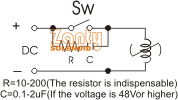
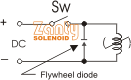
- Protection of Contacts in Driving Circuit.
The control contacts for use with the DC Solenoid may spark, wear and cause noise interference. Provide a proper protection as the case maybe. Resistor & Capacitor Method Diode Insertion Method